Lab 6: Orientation PID
Questions to Consider
Q: What are the potential problems with digital integration?
A: Digital integration involves adding to an accumulator using the last collected data point multiplied by some difference in time. This can cause problems if your sampled data does not properly capture your actual orientation data well enough. Whether it is the robot rotating too fast, or the sampling rate of the IMU being too slow (not as likely), the digital integrator can fail to catch up to real dynamics. Also, if we use gyroscope yaw, the mean of the signal can drift significantly over time, as observed in Lab 2. For the first issue, we have to be cognizant of sampling rates – I should inspect the IMU data to make sure that there aren’t significant jumps in measurement. For the second problem, I plan to implement the IMU’s onboard Digital Motion Processor (DMP), which is an optimized calibration for the IMU.
Q: What are the limitations onboard the IMU gyroscope?
A: According to the datasheet, the gyroscope has sensitivity levels ±250, ±500, ±1000, and ±2000 dps, based on setting the bit GYRO_FS_SEL to 0, 1, 2, and 3 respectively. I selected the highest sensitivity to be sure that we are properly encapsulating all possible rotations on our robot (although it may be overkill). In Arduino, this can be done by calling the library function myICM.setGyroRange(ICM_20948_GYRO_RANGE_2000DPS); if you don’t use DMP, and is automatically set by IMU.enableDMPSensor(INV_ICM20948_SENSOR_GAME_ROTATION_VECTOR); if you do.
Q: Should we use a low-pass filter for the derivative term?
A: After reviewing the data from Lab 5, I realized that the derivative term had huge spikes in values frequently. In the discussion, I had reasoned that it must be because the actual TOF data readings differ from the linear extrapolation and cause big derivatives when it should otherwise be smooth. So to combat that, I thought that I would implement a low pass filter for the derivative term. I realize that creating a class to implement this would be better, since I would need to use it twice, both for the position and angle PID controllers. This should also takes care of derivative kick because sudden changes in setpoint also cause spikes, which would be smoothed out by the LPF. The header for the LPF is as follows (implementation omitted because it is two actual lines of code and a ton of syntactic rubble):
lpf.hpp:
#ifndef LOW_PASS_FILTER_HPP
#define LOW_PASS_FILTER_HPP

class LowPassFilter
{
public:
  LowPassFilter(float alpha);   // Constructor with alpha value
  float update(float newValue); // Update filter with a new value and return new filtered (should be called ONCE every time for new data)
  float getValue() const;       // Get the current filtered value

private:
  float alpha;         // Smoothing factor
  float filteredValue; // Last filtered value
  bool initialized;    // Check if initialized
};

#endif
Q: How can we control direction while moving forward and backward?
A: Currently, my loop separates the calculation and execution of positional and angular PID controllers. But I can instead add the result of the angular PID onto the result of positional PID to create differential drive. However, it may need far less sensitive gains for angle, since it can’t adjust its orientation nearly as fast.
Prelab (Bluetooth Commands)
Like with the last lab, I set up an identical set of commands to set the gains and start PID control, but for angle. I also added in commands to change setpoints and added specificity to the names of the positional PID commands. The complete enum in Arduino is as follows:
enum CommandTypes {
    SET_POS_GAINS,
    SET_POS_SETPOINT,
    START_POS_PID,
    STOP_POS_PID,
    SEND_TOF_DATA,
    SEND_POS_PID_CONTROL_DATA,
    PID_SPEED_TEST,
    PING_SPEED_TEST,
    SET_ANGLE_GAINS,
    SET_ANGLE_SETPOINT,
    START_ANGLE_PID,
    STOP_ANGLE_PID,
};
The method of calling BLE functions in Jupyter are identical to the procedure in Lab 1. To handle the commands, see the following section on refactoring.
Refactoring PID Class
To make a different PID controller for position and angle, I thought it would be best to refactor the PID code, previously done using global variables, into a class so that we can instantiate different objects for position and angle control. This was done by modifying the code from Lab 5, and turning the key PID functions into class methods. As much as I don’t like pasting an entire block of code, I thought it would be best for clarity here:
pid.hpp:
#ifndef PID_HPP
#define PID_HPP

#include "config.hpp" //defines array_size and pid_array_size
#include "lpf.hpp" //import low pass filter class

class PIDController
{
public:
  float setpoint;
  float Kp, Ki, Kd;
  float pid_dt;
  float accumulator;
  float prev_val;

  // pid_index is used on array_size, for slower sensor readings
  int pid_index;
  int pwm_history[array_size];
  int time_array[array_size];   // Stores timestamps for measurements
  float meas_array[array_size]; // Measurement array that stores either angles or distances based on the PID type

  // pid_control_index is used on pid_array_size, for faster control loop.
  int pid_control_index;
  int pid_timestamp_array[pid_array_size];
  float p_array[pid_array_size];
  float i_array[pid_array_size];
  float d_array[pid_array_size];

  bool do_pid;
  unsigned long pid_start_time;
  unsigned long pid_prev_time;

  LowPassFilter derivativeFilter; // LPF for derivative term

  // Constructor
  PIDController(float sp = 0.0, float kp = 0.0, float ki = 0.0, float kd = 0.0, float dt = 0.02, float alpha = 0.1)
      : setpoint(sp), Kp(kp), Ki(ki), Kd(kd), pid_dt(dt), accumulator(0.0), prev_val(-1.0),
        pid_index(0), pid_control_index(0), do_pid(false), pid_start_time(0), pid_prev_time(0), derivativeFilter(alpha) // Initialize LPF with given alpha
  {
    // Initialize arrays to zero
    for (int i = 0; i < array_size; i++)
      pwm_history[i] = 0;
    for (int i = 0; i < pid_array_size; i++)
    {
      pid_timestamp_array[i] = 0;
      p_array[i] = 0.0;
      i_array[i] = 0.0;
      d_array[i] = 0.0;
    }
  }

  /*
   * Sets PID gains dynamically.
   */
  void setGains(float kp, float ki, float kd);

  /*
   * Sets a new setpoint dynamically.
   */
  void setSetpoint(float sp);

  /*
   * Returns a PWM value in [-255, 255]. Negative indicates motor should drive backwards.
   * ONLY CALL THIS ONCE PER LOOP!
   */
  int compute(float pos);

  /*
   * Calculates the linear extrapolation from (timestamp_array[pid_index-2], meas_array[pid_index-2]) (timestamp_array[pid_index-1], meas_array[pid_index-1]).
   * To predict what the next read value should be.
   */
  float linearExtrapolate();

  /*
   * Resets all PID-related parameters and prepares for a fresh PID cycle.
   * The flag PIDController::do_pid should still be set by the BLE command.
   */
  void reset();
};

// Declare two external PID controllers
extern PIDController angle_pid;
extern PIDController pos_pid;

#endif // PID_HPP
pid.cpp:
#include "pid.hpp"
#include "utils.hpp" //implements clamp
#include "lpf.hpp" //implements low pass filter
#include "motors.hpp" //defines MAX_PWM and MIN_PWM

// Initialize two PID controllers
// (float sp = 0.0, float kp = 0.0, float ki = 0.0, float kd = 0.0, float dt = 0.02, float alpha = 0.1)
PIDController angle_pid(0.0, 0.0, 0.0, 0.0, 0.02, 0.3); // Default values, to be adjusted
PIDController pos_pid(304.0, 0.0, 0.0, 0.0, 0.02, 0.5); // Setpoint of 304mm

int PIDController::compute(float pos)
{
  float error = pos - setpoint;
  unsigned long cur_time = millis();

  if (pid_prev_time != 0)
  {
    pid_dt = (cur_time - pid_prev_time) / 1000.0; // sec
  }
  pid_prev_time = cur_time;

  accumulator += error * pid_dt;

  float raw_derivative;

  if (prev_val != -1.000000000)
  {
    // NOT the first iteration -- proceed as normal
    // Anti-derivative kick: replace dError/dt with -dInput/dt (from lab 5)
    raw_derivative = -(pos - prev_val) / pid_dt;
  }
  else
  {
    // the first iteration -- skip Kd term.
    raw_derivative = 0;
  }

  // Apply Low-Pass Filter to the derivative term
  float filtered_derivative = derivativeFilter.update(raw_derivative);
  prev_val = pos; // Save input for -dInput/dt of next loop

  float p = Kp * error;
  float i = Ki * accumulator;
  float d = Kd * filtered_derivative; // Use filtered derivative

  pid_timestamp_array[pid_control_index] = cur_time;
  p_array[pid_control_index] = p;
  i_array[pid_control_index] = i;
  d_array[pid_control_index] = d;
  pid_control_index++;

  return (int)clamp(p + i + d, MIN_PWM, MAX_PWM); //clamp defined in lab 5
}

// Set PID gains dynamically
void PIDController::setGains(float kp, float ki, float kd)
{
  Kp = kp;
  Ki = ki;
  Kd = kd;
}

// Set a new setpoint dynamically
void PIDController::setSetpoint(float sp)
{
  setpoint = sp;
}

// Linear extrapolation based on meas_array and time_array
float PIDController::linearExtrapolate()
{
  // No extrapolation if one data point -- just use that data point
  if (pid_index <= 1)
  {
    return meas_array[pid_index];
  }
  else if (pid_index >= array_size) // Prevent out-of-bounds access
  {
    Serial.println("ARRAY OUT OF BOUNDS REACHED IN LINEAR EXTRAPOLATE");
    return meas_array[array_size - 1];
  }
  else
  {
    float slope = (meas_array[pid_index - 1] - meas_array[pid_index - 2]) /
                  (time_array[pid_index - 1] - time_array[pid_index - 2]); // mm or deg / ms
    float local_dt = millis() - time_array[pid_index - 1];                 // ms
    Serial.print("Result of linear extrapolation: ");
    Serial.println(meas_array[pid_index - 1] + slope * local_dt);
    return meas_array[pid_index - 1] + slope * local_dt;
  }
}

void PIDController::reset()
{
  pid_dt = 0.02; // s, default value
  accumulator = 0.0;
  prev_val = -1.0; // Init as invalid TOF reading to discern first iter

  pid_index = 0; // Sets return array index to 0
  pid_control_index = 0;

  for (int i = 0; i < array_size; i++)
  {
    time_array[i] = 0; // Replacing old timestamp array
    pwm_history[i] = 0;
    meas_array[i] = 0.0; // Replacing old distance1_array
  }

  for (int i = 0; i < pid_array_size; i++)
  {
    pid_timestamp_array[i] = 0;
    p_array[i] = 0.0;
    i_array[i] = 0.0;
    d_array[i] = 0.0;
  }

  pid_start_time = millis();
}
Some key differences from the implementation in Lab 5:
- The function to translate the PID output into motor actuation was moved to a different file
motors.hpp, which was needed since our execution strategy would be different between position and angle PID. - All stored data now belongs to the class, instead of using TOF distance1_array, which groups data storage together more logically.
- The reset() function now resets everything related to the controller, instead of just temporary variables as implemented in Lab 5.
Other than that, the code effectively functions identically. In handle_command(), I keep it very short and simple for the new angle commands:
case SET_ANGLE_GAINS:
  {
    float kp_val, ki_val, kd_val;
    bool success_kp = robot_cmd.get_next_value(kp_val);
    bool success_ki = robot_cmd.get_next_value(ki_val);
    bool success_kd = robot_cmd.get_next_value(kd_val);

    if (success_kp && success_ki && success_kd)
    {
      angle_pid.setGains(kp_val, ki_val, kd_val);
      Serial.println("Angle PID gains set successfully.");
    }
    else
    {
      Serial.println("Failed to set Angle PID gains. Ensure all values are provided.");
    }
    break;
  }

  case SET_ANGLE_SETPOINT:
  {
    float set;
    bool success_set = robot_cmd.get_next_value(set);

    if (success_set)
    {
      angle_pid.setSetpoint(set);
      Serial.println("Angle setpoint set successfully.");
    }
    else
    {
      Serial.println("Failed to set Angle Setpoint");
    }
    break;
  }

  case START_ANGLE_PID:
  {
    angle_pid.do_pid = true;
    angle_pid.reset();
    break;
  }
  case STOP_ANGLE_PID:
  {
    angle_pid.do_pid = false;
    stop();
    break;
  }
Implementing DMP for Yaw Angle
For angle PID, I need an effective way to get the yaw angle. As discussed above, the built-in DMP is the best way to get a reliable reading for yaw because there isn’t an easy way to design a complementary filter for it using what we’ve learned in this course. To implement DMP, I followed the tutorial on the class repository, while also referring Stephan’s writeup from which the tutorial was inspired by.
I won’t repeat the tutorial in this writeup, but I wanted to highlight my debugging points for Windows users during the setup, since Stephan uses Mac settings for his writeup.
When installing Node.js via Powershell, you may run into the issue that node is not recognized:
// After 'fnm install 22', for Node.js:
(base) PS C:\Users\user> node -v
node : The term 'node' is not recognized as the name of a cmdlet, function, script file, or operable program.
This is fixed by calling the line fnm env --use-on-cd | Out-String | Invoke-Expression to add fnm to the environment. But more permanently, we can write this config to automatically enable on startup using:
echo 'fnm env --use-on-cd | Out-String | Invoke-Expression' >> $PROFILE

//After calling above:
(base) PS C:\Users\user> node -v
v22.14.0
(base) PS C:\Users\user> npm -v
10.9.2
The serial port that I had to change to was 'COM3', which is the same as what displays in Arduino IDE when the MCU is connected. If you get an error saying COM3 access is denied, make sure all other instances of COM3 are closed, including Arduino Serial monitor.
With the setup complete, I could create a function that fetches the DMP yaw value. Since the DMP function should return within range of (-180, 180), I use values with magnitude greater than 360 to represent different status code returns.
/*
* Reads Quat6 data from DMP and converts into Euler Angle.
* Returns: [yaw], the yaw angle in degrees, in absolute orientation, the result of converting the Quat6 data from DMP.
* Returns: 404. , if the DMP FIFO has no data available. Use previous data point in that case or extrapolate.
* Returns: 1000. + sensor status, if the sensor status is not OK.
* Returns: -666.0, if myICM.status is unexpected (default return).
*/
float getDmpYaw(){
  // From Example7_DMP_Quat6_EulerAngles, taken from Stephan's tutorial.
  // https://github.com/FastRobotsCornell/FastRobots-2025/blob/main/docs/tutorials/dmp.md

  icm_20948_DMP_data_t data;
  myICM.readDMPdataFromFIFO(&data);

  // Keep reading until we get to the latest element in the FIFO queue, with a limit of [maxReads] times.
  int maxReads = 10;
  while (myICM.status == ICM_20948_Stat_FIFOMoreDataAvail && maxReads-- > 0){
    myICM.readDMPdataFromFIFO(&data);
  }

  if (myICM.status == ICM_20948_Stat_FIFONoDataAvail){
    return 404404.;
  }

  if ((myICM.status == ICM_20948_Stat_Ok) || (myICM.status == ICM_20948_Stat_FIFOMoreDataAvail)) {
      // We have asked for GRV data so we should receive Quat6
      if ((data.header & DMP_header_bitmap_Quat6) > 0) {
          double q1 = ((double)data.Quat6.Data.Q1) / 1073741824.0; // Convert to double. Divide by 2^30
          double q2 = ((double)data.Quat6.Data.Q2) / 1073741824.0; // Convert to double. Divide by 2^30
          double q3 = ((double)data.Quat6.Data.Q3) / 1073741824.0; // Convert to double. Divide by 2^30
          double q0 = sqrt(1.0 - (q1 * q1 + q2 * q2 + q3 * q3));

          // Convert the quaternion to Euler angles. We only need [yaw], but all 3 here for completeness.
          // double roll = atan2(2.0 * (q0 * q1 + q2 * q3), 1.0 - 2.0 * (q1 * q1 + q2 * q2));
          // double pitch = asin(2.0 * (q0 * q2 - q3 * q1));
          double yaw = atan2(2.0 * (q0 * q3 + q1 * q2), 1.0 - 2.0 * (q2 * q2 + q3 * q3));

          // Convert radians to degrees
          // roll *= 180.0 / M_PI;
          // pitch *= 180.0 / M_PI;
          yaw *= 180.0 / M_PI;

          // REQUIRED ADJUSTMENT: See code snippet below

          return yaw;
      }
  }
  // myICM status is not ok, should also not reach because MoreDataAvail and NoDataAvail are both checked for..
  else if (myICM.status == ICM_20948_Stat_WrongID){
    return 100000. + myICM.status; //bad
  }

  return -66666.; //default return value, should not reach.
}
Note that the DMP returns values in the range of [-180, 180], which causes wrap-around error spikes as readings go from -179. to 179.. Therefore, we need to add the following snippet before returning yaw.
//Global variables, outside of getDmpYaw()
float lastValue = 0.;
bool lastValueInitialized = false;

//in getDmpYaw(), between yaw calculation and its return:

// Changes output from [-180, 180] to any angle by assuming continuity (the last value cannot differ by more than 180. than the current value naturally).
// The value 180. was obtained through trial and error (but you can guess that the car will not turn 180. deg in 1/55 sec).

if (!lastValueInitialized){
  lastValue = yaw;
  lastValueInitialized = true;
  return yaw;

} else {
  //Assume that the 55Hz sensor isn't moving 180. degrees between measurements
  while (yaw - lastValue >= 180.) {
    yaw -= 360.;
  }
  while (yaw - lastValue <= -180.) {
    yaw += 360.;
  }
  lastValue = yaw;
}
Also, using the DMP means that I unfortunately do have to take the derivative of a signal that is the integral of the gyroscope reading, because it outputs an absolute orientation angle. Good thing is, this allows me to use generalized PID controller code for both position and angle.
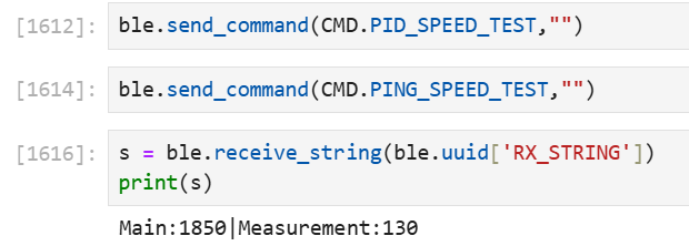
Speed of Sensor vs. Speed of Control Loop
Like in lab 5, I used a bluetooth command to initiate a “speed test” to gauge how fast my sensor is returning values vs. how fast the control loop is running. I recycle the same bluetooth command, so the handling code is almost the same, except I change out the TOF call with a DMP call:
void anglePidControlLoop()
{
  if (doSpeedTest)
  {
    controlLoopCounter++;
    float yaw = getDmpYaw();
    if (isValidYaw(yaw)) measurementCounter++;

    if (millis() - testStartTime > 2000)
    {
      doSpeedTest = false;
    }
    return;
  }

  //... rest of PID control
}
I ran the speed test for 2 seconds, and we can see that the angular data comes in much faster than the TOF data. However, the rates are still an order of magnitude different, so decoupling the control loop from the angular measurement is still as necessary as ever.
Execution of PID
Executing the PID code was offloaded to a function defined within my motors.hpp file. For angle, I realized that I don’t want to stop once my PWM is low because there is no danger of hitting a wall. We should instead tune out the oscillations with Kd. So I kept the execution code simple:
void executeAnglePid(int pwm)
{
  if (pwm > 0)
  {
    pwm += DEADBAND;
    spin(RIGHT, (int)clamp(pwm, MIN_PWM, MAX_PWM));
  }
  else //pwm < 0, so need to negate
  {
    pwm -= DEADBAND;
    spin(LEFT, -((int)clamp(pwm, MIN_PWM, MAX_PWM)));
  }
}
PID Tuning
I started tuning initially by using disturbance rejection and how well the car performed as an initial metric of success. So I keep the setpoint at 0 degrees, then during each iteration of gains, I kick the robot both counterclockwise and counterclockwise to see how well the orientation recovers. Since it is hard to visually tell orientation due to the translational motion, I used plots to quantify whether or not the controller works well. I also put a lower-friction craft tape on my wheels so that it would mostly remain in place while it spun (and so I could test it outside of lab on any surface and have mostly similar results). Although, I noted that this means we may undershoot our parameters, since we would need more motor input to turn on rubber.
Initial Tuning Process (Tape)
Later on, I had to take the tape off because the lack of friction meant that the overshoot was unbearably large (since it couldn’t reverse). I will keep the tuning process in here because the general concepts still apply, except that with rubber, we will need a higher Kp and Ki to overcome friction, while needing a smaller Kd because the friction acts as a damper already.
First, I started with Kp = 1, Ki = 0, Kd = 0. I thought back to the open loop testing in lab 4, and noticed that differential spinning usually took a higher PWM to get started. And since there was no risk of bumping into walls, I could start higher in values.
Then, I tried to make the angle approach 0 faster by upping Kp, but that caused instability.
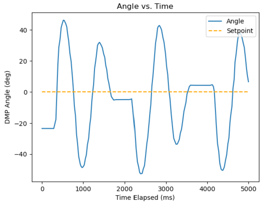
After that, I tried to add derivative in an attempt to add a damping factor, starting with Kp = 0.2. Note that I tried using a higher alpha for low-pass, but it quickly became unstable. So I had to heavily low pass the derivative signal, using alpha = 0.01:
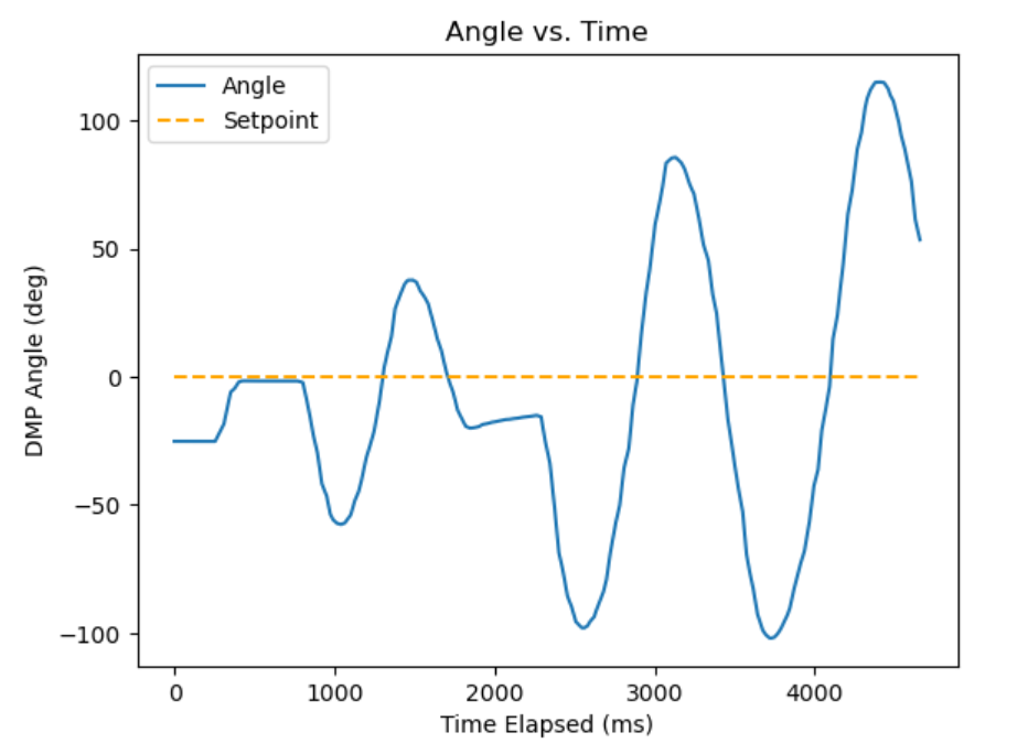
Then, increasing Kd to 1 seemed better in reaching 0, but the instability still happens:
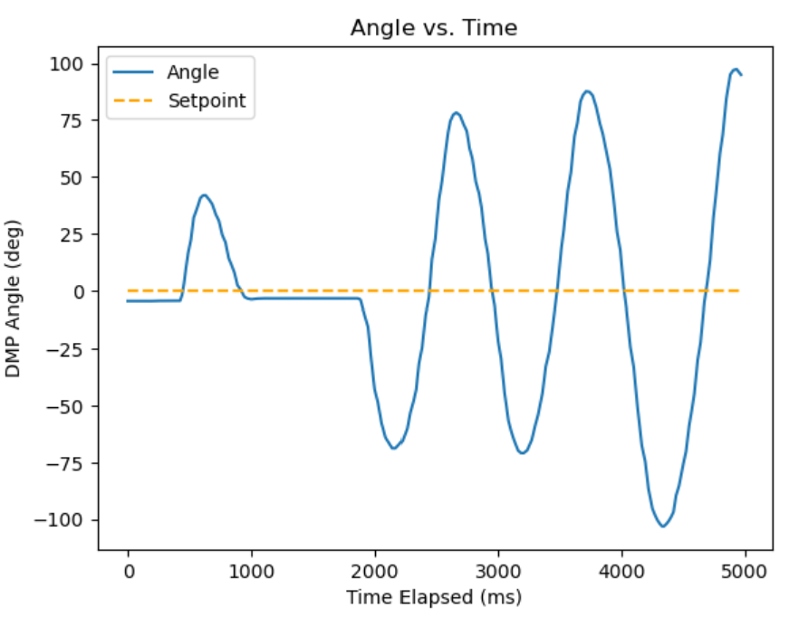
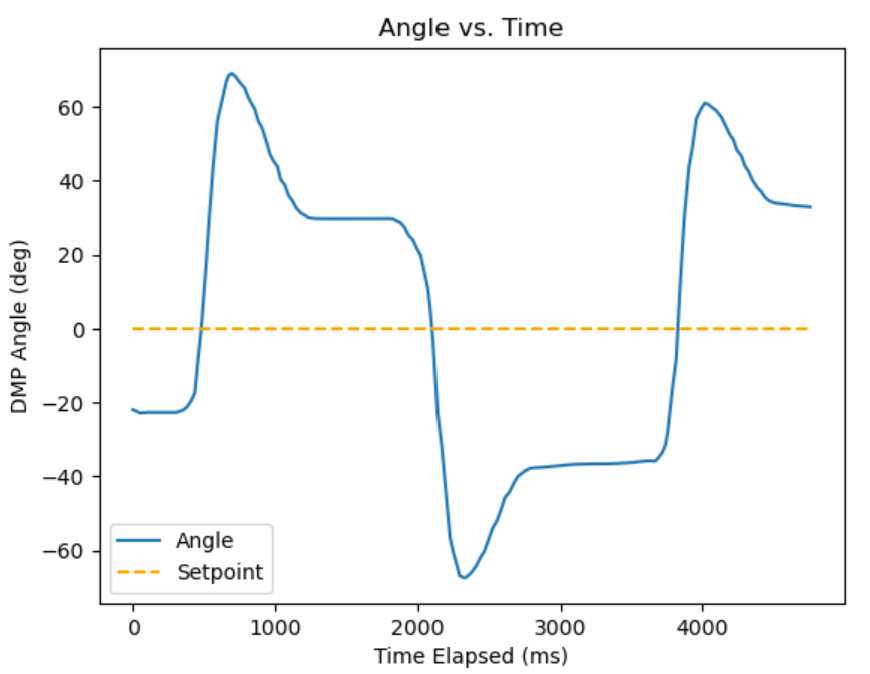
Then, I knew I had to back off Kp to hopefully not initiate the unsteady behavior. After that, I added a Ki term to get closer to the error since the Kp term was now weaker than before. This gave me a good enough result to move onto setpoint testing.
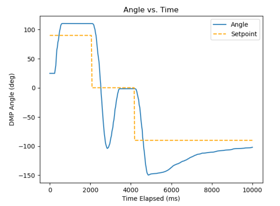
Initially, I did the routine by setting the setpoint to 90, 0, and -90 degrees. This was done by executing the Jupyter commands in series:
ble.send_command(CMD.SET_ANGLE_GAINS, "1.5|0.5|1") #P, I, D
ble.send_command(CMD.SET_ANGLE_SETPOINT, "90") #deg
ble.send_command(CMD.START_ANGLE_PID,"")
time.sleep(2)
ble.send_command(CMD.SET_ANGLE_SETPOINT, "0") #deg
time.sleep(2)
ble.send_command(CMD.SET_ANGLE_SETPOINT, "-90") #deg
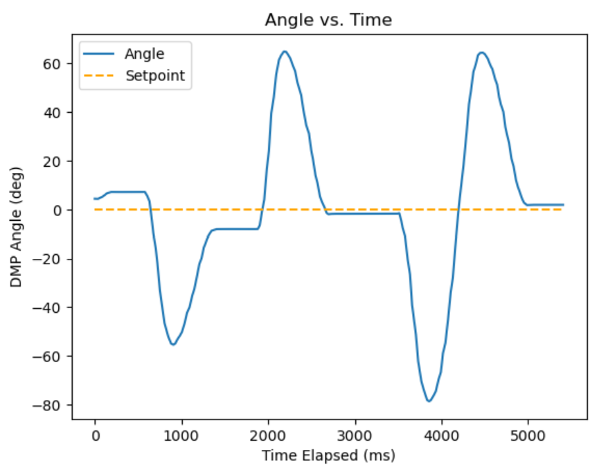
This gave me the resulting graph, which I was pretty happy with. We can see that there is slight overshoot on the 90 degrees setpoint, which it presumably would have crept towards with its integral term since it does so at the end for the -90 degree setpoint. There is a decent amount of overshoot for the 0 degree setpoint but it converges to the setpoint with little error. The end behavior shows that eventually it reaches steady state.
However, I didn’t get a video of this and also felt that this low friction didn’t really match real use cases, so I continued tuning with the bare wheels.
Further Setpoint Tuning (Rubber)
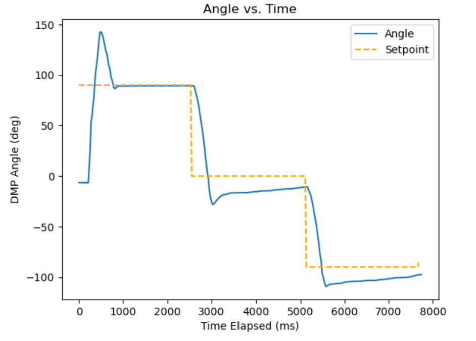
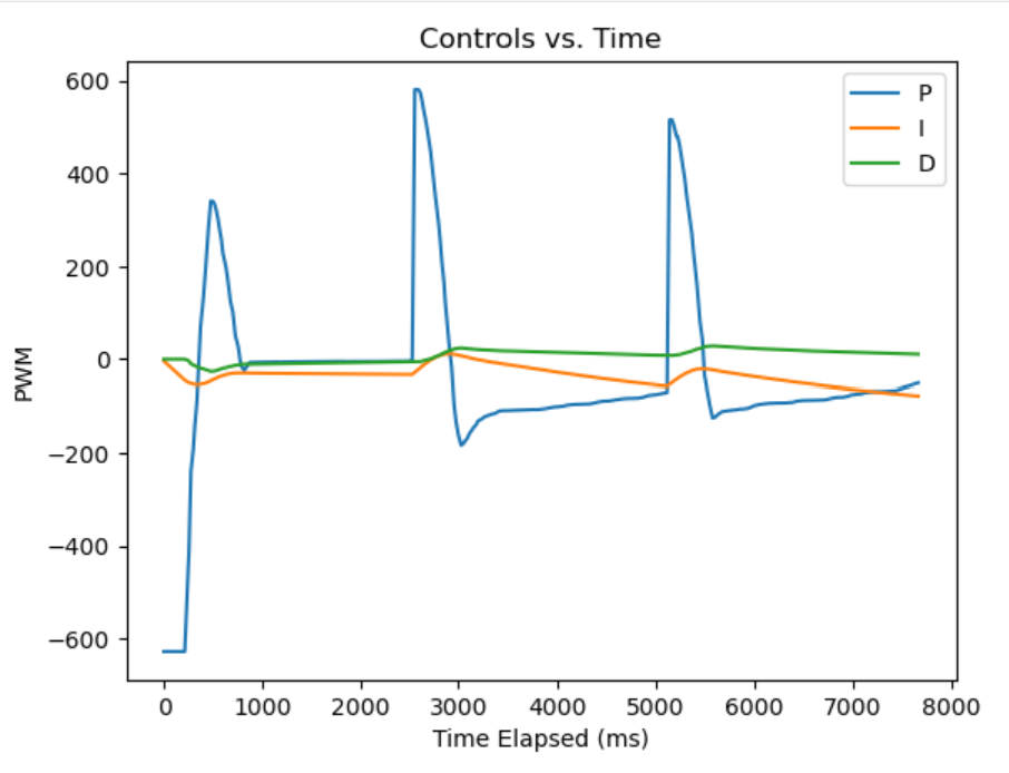
Like mentioned above, I increased Kp, Ki to account for higher friction and lowered Kd. I increased the timing of the sleep in Python to 2.5 seconds for the higher friction, and I tuned until I got this attempt:
The graphs for position and controls are as follows: