Lab 1: Artemis and Bluetooth
Lab 1A: Artemis
In this lab, we installed and tested tested the Arduino IDE, including the corresponding libraries required to connect the RedBoard Artemis Nano that we will be using throughout the semester.
Prelab
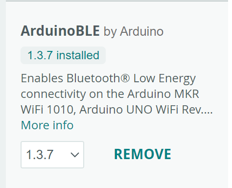
I already had the latest major version of the Arduino IDE version 2.3.4 installed from previous classes. I just had to install the ArduinoBLE library to proceed with the lab.
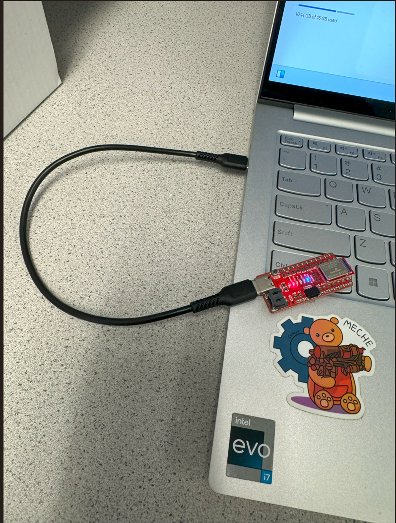
Task 1: Hook up the Artemis Board
Task 2: Blink
As per lab instruction, I directly used the blink example code (File->Examples->01.Basics/Blink) from Arduino, which simply makes the built-in LED toggle its state every second. This was a promising first demonstration that the Artemis was able to connect to my laptop and that the IDE environment works. Below is a video showing the Artemis LED blinking.
Task 3: Serial Print
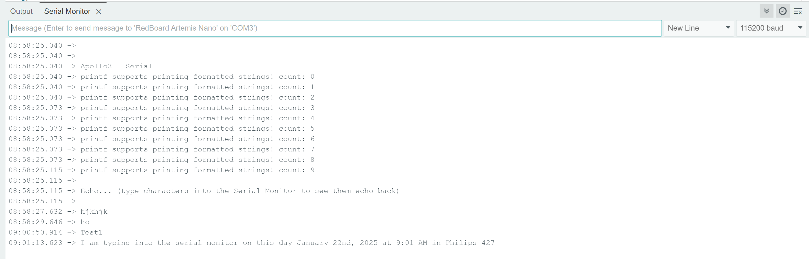
Next, I verified two way serial communication using the example code (File->Examples->Apollo3/Example04_Serial). The code makes it so that any input typed into the serial monitor would be echoed back. The only configuration I had to change was my baud rate, which needed to be 115200 as specified in the code. Below is a screenshot of the Serial monitor showing a very specific message to demonstrate that it was an input from me, which the Artemis echoed back.
Task 4: Temperature Sensor
The next task was to use the example code (File->Examples->Apollo3/Example02_AnalogRead). The code uses the Arduino analogRead() method to read the analog voltage level corresponding to temperature, then prints it to serial. Below is a video of me palming the board, which causes the temperature reading to increase.
Task 5: Microphone
The final task in Lab 1A was to use the example code (File->Examples->PDM/Example1_MicrophoneOutput) to print the highest frequency detected from the microphone aboard the Artemis. To verify this, I snapped into the microphone, which produces a much higher-frequency sound than the ambient noise in the lab. Below is a video showing the Arduino output as I snapped.
Lab 1B: Bluetooth
Prelab
For this lab, I had a ton of trouble getting Jupyter to properly start. After following the steps:
python3 -m pip install --user virtualenv
python3 -m venv FastRobots_ble
.\FastRobots_ble\Scripts\activate
pip install numpy pyyaml colorama nest_asyncio bleak jupyterlab
jupyter lab
I kept repeatedly getting the error OSError: [WinError 10038] An operation was attempted on something that is not a socket. To attempt a fix at this, I first troubleshooted by re-installing all of the key things involved in setting up a virtual environment, Python, and Jupyter. I originally had Python versions 3.10 and 3.11 installed from other work I’ve done on this computer, so I removed all of that and downloaded the latest version 3.13 from the Microsoft store. I deleted and re-created the virtual environment several times, and also moved around the contents from the ble_robot_1.2 to see if that changed anything. Then, seeing that the error cited referred to failure to start up a socket, I figured I should uninstall and reinstall Tornado, the socket manager for Jupyter. But despite all that, the error didn’t go away.
For the rest of the lab section, I searched specific parts of the error message to see if other users online had encountered this issue. The StackOverflow and scientific computing forum pages I checked had no solutions, but ultimately I found a report of a similar issue on the Jupyter GitHub issues page, in issues 1832 and 5435. The former notified me that it could potentially be an issue having to refer to the IP 127.0.0.x directly instead of localhost, and the latter gave me the steps to fix it. To solve the issue, I had to create the config file for Jupyter to explicitly navigate to 127.0.0.x. First, I ran
jupyter lab --generate-config to generate a config file. Then, I navigated to ~/.jupyter/jupyter_notebook_config.py and uncommented the line c.ServerApp.ip = localhost, replacing “localhost” with “127.0.0.1”. After this, repeating the steps in the prelab successfully opened up Jupyter lab and I was able to proceed.
For the rest of the setup, I need connect the Artemis’s MAC address to my computer. When the Artemis first connects to the Arduino BLE, and the ble_arduino.ino sketch from the ble_robot_1.2 folder is burned into the board, it prints the MAC address to serial:
21:16:46.809 -> Advertising BLE with MAC: c0:81:98:26:c:64
Then I needed to create a UUID to identify my computer and the data being sent between by computer and the Artemis. In demo.ipynb, I ran the code:
from uuid import uuid4
uuid4()
With both of these identifiers, I made the changes to connections.yaml in the ble_python repository, swapping out the information on the lines:
artemis_address: 'c0:81:98:26:c:64'
ble_service: '6fa632ca-6d84-4823-af1f-40a50ae188a6'
And in ble_arduino.ino, I changed the following line:
#define BLE_UUID_TEST_SERVICE "9A48ECBA-2E92-082F-C079-9E75AAE428B1"
To wrap up the setup, I ran through all of the blocks in demo.ipynb and verified that the actual outputs matched with the expected results outlined in the notebook. To make connecting easier after uploading code to the Artemis each time, I copied the block used to connect to the Artemis, along with reimporting CMD (since it changes after almost every task), and placed it in front of where I would write the rest of my code.
ble = get_ble_controller()
ble.connect()
from cmd_types import CMD
Task 1: Echo
The first task was to make the ECHO command return, from the Artemis to my laptop, an augmented string containing the original message. This task set me up with expectations for the general workflow in this lab – I would add a command or verify that a command existed in cmd_types.py and on top of the file in ble_arduino.ino, then write code to handle the command in the switch-case found in ble_arduino.ino.
In ble_arduino.ino, I referred to how strings were returned in the PING command in a previous case and wrote the following:
...
case ECHO:
  char char_arr[MAX_MSG_SIZE];

  // Extract the next value from the command string as a character array
  success = robot_cmd.get_next_value(char_arr);
  if (!success)
      return;

  //Using the ping example, we clear the tx_estring and append the string we receive from computer
  tx_estring_value.clear();
  tx_estring_value.append("Robot says -> ");
  tx_estring_value.append(char_arr);
  tx_characteristic_string.writeValue(tx_estring_value.c_str());

  Serial.print("Sent back: ");
  Serial.println(tx_estring_value.c_str());
  break;
...
In Jupyter, the code and output looks like:

Task 2: Send Three Floats
For this task, we need to write Arduino code to extract values from the SEND_THREE_FLOATS command. In ble_arduino.ino, I processed the command and print the three floats to Serial:
case SEND_THREE_FLOATS:
  float fa, fb, fc;
  // Extract the three floats
  success = robot_cmd.get_next_value(fa);
  if (!success)
      return;
  success = robot_cmd.get_next_value(fb);
  if (!success)
      return;
  success = robot_cmd.get_next_value(fc);
  if (!success)
      return;

  Serial.print("Three floats: ");
  Serial.print(fa);
  Serial.print(", ");
  Serial.print(fb);
  Serial.print(", ");
  Serial.println(fc);

  break;
The following screenshots show the command sent in Jupyter, as well as its response in Arduino serial monitor.


Task 3: Get Time Millis
In this task, we were asked to create a new command GET_TIME_MILLIS to return a timestamp in a string similar to “T:123456”. To do this, I add a new command in cmd_types.py:
class CMD(Enum):
    ...
    GET_TIME_MILLIS = 6 # Task 3
...
…and at the top of ble_arduino.ino:
enum CommandTypes
{
    ...
    GET_TIME_MILLIS,
    ...
};
Then, I added the code in ble_arduino.ino to handle this command, simply using millis() to fetch a timestamp and returning it:
case GET_TIME_MILLIS:
  tx_estring_value.clear();
  tx_estring_value.append("T:");
  // Typecast millis() from unsigned long to double for the append(float value) method
  tx_estring_value.append((double) millis());
  tx_characteristic_string.writeValue(tx_estring_value.c_str());

  Serial.print("Sent: ");
  Serial.println(tx_estring_value.c_str());
  break;
The following screenshot shows the call and output in Jupyter:

Task 4: Notification Handler
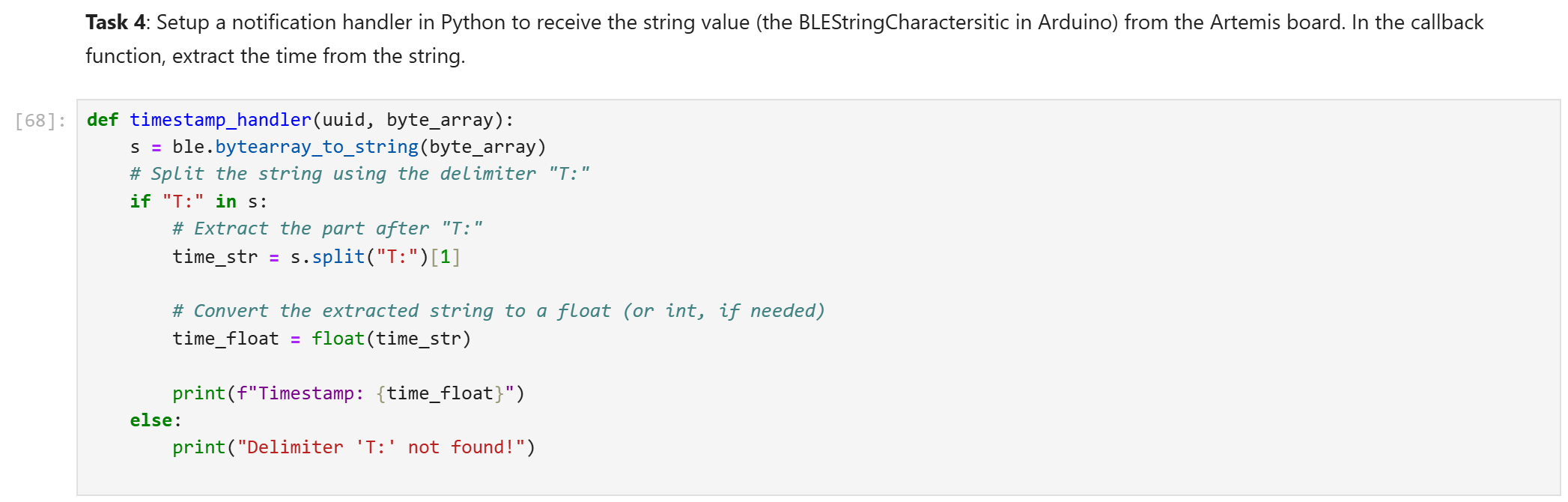
To design a notification handler, I referenced the documentation in the demo.ipynb file, which stated that the handler must have two arguments: the UUID object and the byte_array sent back by the Artemis. The string sent is stored in the byte_array, where helper functions are already defined to convert them to a string. From there, all I had to do was split on the metadata I attached earlier in task 3, the substring “T:”. The screenshot below shows the definition of my callback function.
Task 5: Loop Get Millis
Task 5 was to design a loop in Arduino to continually be sent over to my laptop for processing. Since this effectively creates an asynchronous interaction between the laptop and Artemis, we have to use the notification handler above to handle responses from the Artemis. In addition to that, we define a new command to tell the Artemis when to start the loop, named SPEED_TEST because the question after asks about the data transfer rate:
class CMD(Enum):
    ...
    SPEED_TEST = 7 # Task 5
...
… and at the top of ble_arduino.ino:
enum CommandTypes
{
    ...
    SPEED_TEST,
    ...
};
In the switch-case, I handle the command by repeatedly sending the timestamp data to my laptop for three seconds, as defined by the loop guard in the while-loop. From this task onward, I neede to add the explicit {} around the case as to prevent the local variable initial_time from flowing downward in the following cases. The code goes as follows:
case SPEED_TEST:
  // Wrap in explicit {} to prevent jump to case label compilation error
  {
    unsigned long initial_time = millis();
    // Keep responding within three seconds...
    while (millis() - initial_time < 3000){
      tx_estring_value.clear();
      tx_estring_value.append("T:");
      // Typecast millis() from unsigned long to double for the append(float value) method
      tx_estring_value.append((double) millis());
      tx_characteristic_string.writeValue(tx_estring_value.c_str());

      Serial.print("Sent: ");
      Serial.println(tx_estring_value.c_str());
    }
    break;
  }
To execute this command, we need to start the notification system with our handler beforehand. The screenshot below shows the call and a portion of the responses in Jupyter. (Note that the start_notify() block was used in following tasks as well, so the execution order to the left of the blocks seems out-of-order, but that block was called before executing the SPEED_TEST command):
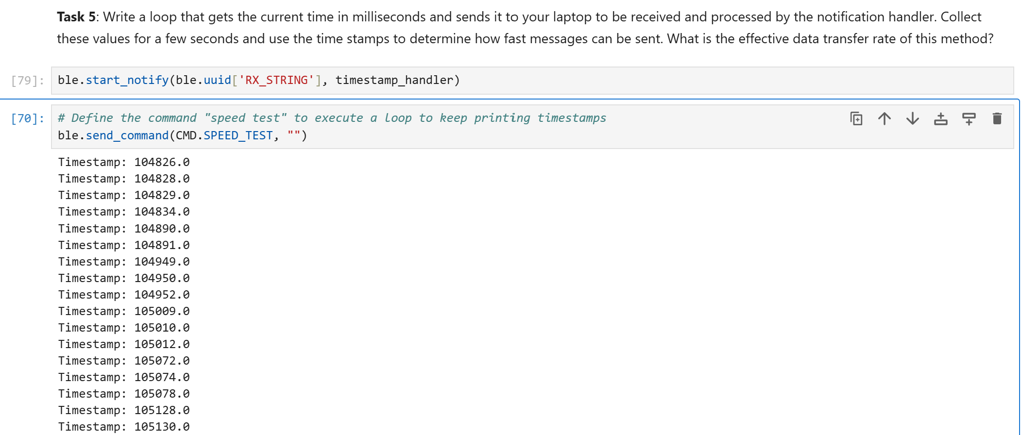
I pasted the output into Excel to count the number of entries. We got 140 timestamp messages in 3000 milliseconds. Each message was a string of length 10 (including the ‘T’, ‘:’, and ‘.’ characters). So the transfer rate we can glean from this is (140 messages * 10 bytes) / 3 seconds = 466.7 bytes per second.
Task 6: Timestamp Array
This task asks us to loop and store timestamps again, except we store the results in an array on the Artemis and transfer the data over after all values have been gathered. To do this, I first have to define the command SEND_TIME_DATA:
class CMD(Enum):
    ...
    SEND_TIME_DATA = 8 # Task 6
...
… and at the top of ble_arduino.ino:
enum CommandTypes
{
    ...
    SEND_TIME_DATA,
    ...
};
Then, in Arduino, I needed to define a global array (so that other nmethods can access it as necessary) to store timestamps. The array size is entirely arbitrary, but I felt like 1000 was a nice round number. At the top of the file:
...
const int array_size = 1000;
int timestamp_array[array_size];
//////////// Global Variables ////////////
...
In the switch-case, I handle this command by looping for a set amount of time, defined by a while-loop that continues until the difference from an initial time exceeds a threshold, which is 100 ms. I purposefully chose a small period of time, at least compared to the previous task, because array writes should be comparably very fast. By picking a lower amount of time to run for, I was hoping to reduce the risk of running out of space in my array. The code goes as follows:
case SEND_TIME_DATA:
  // Wrap in explicit {} to prevent jump to case label compilation error
  {
  unsigned long initial_time = millis();
  int i = 0; // index thru timestamp_array
  // Build array for 100 ms (I expect a write to memory to be MUCH faster than sending message)
  // Also, timestamp_array stores ints to take up less than floats or UL, since I've noticed millis() returns integers
  while (millis() - initial_time < 100) {
    if (i < array_size){
      timestamp_array[i] = (int) millis();
      i++;
    }
    else {
      Serial.print("Memory exceeded, the ");
      Serial.print(i);
      Serial.println("-th element could not be written.");
      i++;
    }
  }

  //Loop through and return the array
  for (int j = 0; j < array_size; j++) {
    tx_estring_value.clear();
    tx_estring_value.append("T:");
    // Typecast millis() from unsigned long to double for the append(float value) method
    tx_estring_value.append(timestamp_array[j]);
    tx_characteristic_string.writeValue(tx_estring_value.c_str());
    }
  }
  break;
The else branch in the code prints to serial if the array overflows, but it never reached since nothing was printed on the serial monitor when the command was sent.
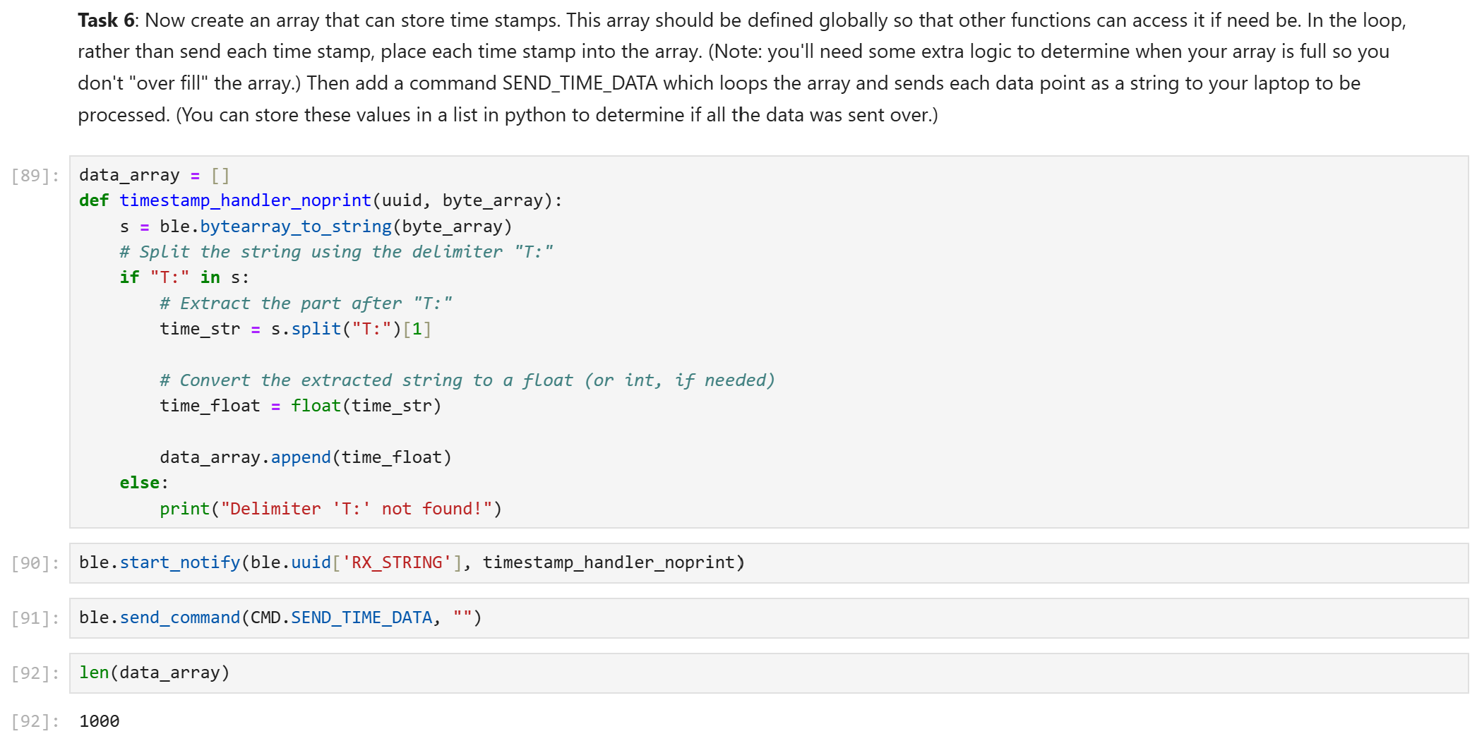
Finally, this screenshot from Jupyter shows the command call. I defined a new notification handler so it wouldn’t print 1000 elements. I check the length of the array transferred after the execution finishes to make sure the entire array has been written from Arduino.
Task 7: Send Temp Data
For this task, we have to simultaneously sample the timestamp and sample, storing both in a two associated arrays. The flow is almost identical to the previous task, adding a new command first:
class CMD(Enum):
    ...
    SEND_TEMP_DATA = 9 # Task 3
...
… and at the top of ble_arduino.ino:
enum CommandTypes
{
    ...
    SEND_TEMP_DATA,
    ...
};
Then, we add another global array to the top of ble_arduino.ino:
const int array_size = 1000;
int timestamp_array[array_size];
float temperature_array[array_size]; // <--- Task 7
//////////// Global Variables ////////////
In the switch-case, we do the same as the previous task, except we assign to the time and temperature arrays simultaneously using both the millis() and the getTempDegF() functions, respectively. In the return, we concatenate together the time and temperature in one line, separated by the divider character |. The code in ble_arduino:
case SEND_TEMP_DATA:
  // Wrap in explicit {} to prevent jump to case label compilation error
  {
    unsigned long initial_time = millis();
    int i = 0; // index thru both time and temp arrays
    // Build array for 100 ms
    // Also, timestamp_array stores ints to take up less than floats or UL, since I've noticed millis() returns integers
    while (millis() - initial_time < 100) {
      if (i < array_size){
        timestamp_array[i] = (int) millis();
        temperature_array[i] = (float) getTempDegF();
        i++;
      }
      else {
        Serial.print("Memory exceeded, the ");
        Serial.print(i);
        Serial.println("-th element could not be written.");
        i++;
      }
    }

    //Loop through and return the arrays
    for (int j = 0; j < array_size; j++) {
      tx_estring_value.clear();
      tx_estring_value.append("Time:");
      tx_estring_value.append(timestamp_array[j]);
      tx_estring_value.append("|");
      tx_estring_value.append("Temp:");
      tx_estring_value.append(temperature_array[j]);
      tx_characteristic_string.writeValue(tx_estring_value.c_str());

    }
    break;
  }
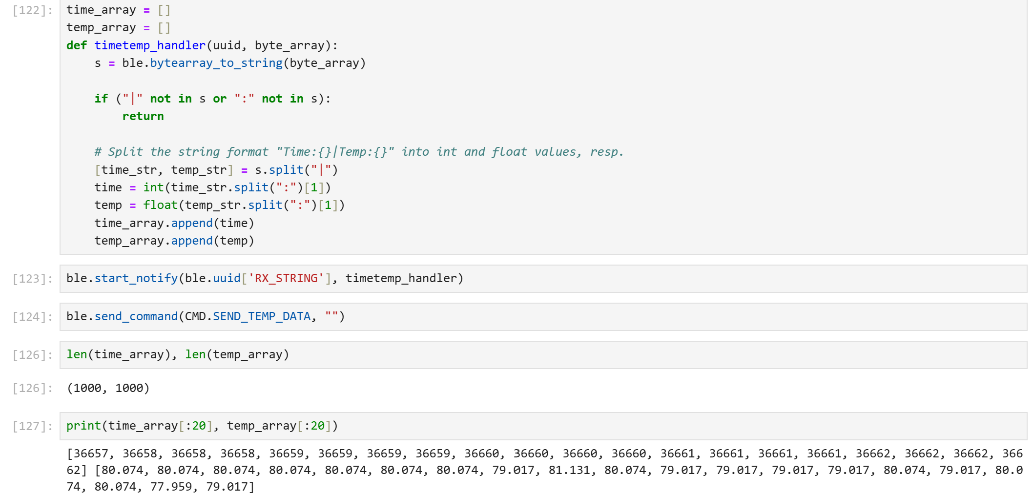
The Jupyter call for this creates a new notification handler again to populate two lists instead of one. I check the length and a few elements of the return lists to make sure that the data was properly transfered.
Task 8: Discussion of Differences
The difference between tasks 5 and 6 is in when the data samples are being recorded vs. when they are being transmitted. In task 5, a continuous loop collects data and then transmits it to the laptop. This method of transmission would be useful if, for example, we were collecting live sensor data on our robot. In that case, live communication would be more important than collecting as many data points as possible. An advantage of this method is that it requires no additional space to store the data since it is being immediately sent to the processing computer. However, the drawback is that this method is very slow and may not be suitable for high-frequency sensors.
On the contrary, in task 6, the first for loop collects all of the data in a rapid burst, then the second for loop slowly transmits the data from the Artemis to the laptop. This method would be useful if we needed to measure values that changed incredibly quickly over a short period of time because the data recording happens at a much faster pace. The drawback of the faster sampling rate is that the data must be stored onboard the Artemis, taking up valuable space until the data is transmitted.
From the snippet in task 7 where I printed select elements of the return array, we can see taht there were three data points for each millisecond data entry. That implies a sampling rate of 3000 entries / second.
The Artemis board has 384 kB of RAM. From the screenshot below, I assume the code takes up approximately the same amount of space as our current ble_arduino.ino file does, and that all remaining 355064 bytes are used to store data. If we use floats for each data value, we can store 355064/4 = 88766 values before completely running out of space.
Discussion
In the prelab for lab 1B, I’ve gained some experience debugging setting up code environments. In terms of technical skills, I learned how to use BLE to wirelessly transmit information from a microcontroller to a separate processing computer. I also learned about two methods of transmitting data: transmitting as you sample, which is better for live communication, and transmitting after-the-fact, which is better for faster sampling rates.
Acknowledgements
- I referenced Mikayla Lahr and Nila Narayan’s pages from last year for a reference on how to format my lab writeup.
- Special thanks to Steven Sun for clarifying how to start on Task 5, as well as general help on getting a Jekyll template to work for this website.