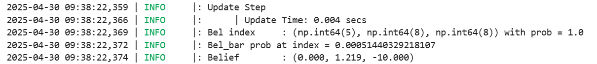
Lab 11: Localization on the Robot
Verifying the Simulation
To make sure the robot can interface with the computer in an optimal way, we were provided with optimized simulation code like what we did in Lab 10. To verify that the simulation code works as expected, I ran the simulation once and compared the final plot of ground truth (green), Bayes filter prediction (blue), and odometry (red) to what I saw previously.
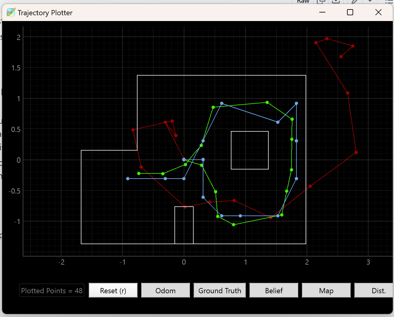
This matches fairly well with the result in the previous lab.
Implementing the Update Step on the Real Robot
The motion of our robot is too noisy to execute the prediction step of the Bayes filter using any meaningful motion model. The motion model would simply depend on too many factors, such as motor asymmetry, wheel traction, or battery percentage. Particularly, my robot would be especially noisy given how many times I’ve dropped it from great heights. Also, it is difficult to iterate the Bayes filter in motion because there is no good mechanism to autonomously retrieve a ground truth. Therefore for this lab, we will localize one position by getting real data from the robot and calling the update step once, with the goal of comparing the performance between theoretical and experimental localization.
First, to interface between the robot and the processing computer better, I modified the command from Lab 9 to take in arguments for:
- How much to increment setpoint by between measurements (in degrees)
- Number of measurements to take at each setpoint
- The acceptable +-error before the PID Controller halts (Idea courtesy of Stephan Wagner)
The differences from Lab 9 are the extra inputs for incr, error, and num_readings, which are passed into the routine-executing mappingSequence().
case START_MAPPING:
{
  // Read gain inputs
  float kp_val, ki_val, kd_val;
  bool success_kp = robot_cmd.get_next_value(kp_val);
  bool success_ki = robot_cmd.get_next_value(ki_val);
  bool success_kd = robot_cmd.get_next_value(kd_val);

  if (success_kp && success_ki && success_kd){
    Serial.println("START MAPPING: Angle gains set successfully");
    angle_pid.setGains(kp_val, ki_val, kd_val);
  }
  else{
    Serial.println("Failed to set angle PID gains -- START_MAPPING");
  }

  // Read mapping settings
  float incr, error;
  int num_readings;
  bool success_incr = robot_cmd.get_next_value(incr);
  bool success_error = robot_cmd.get_next_value(error);
  bool success_num_readings = robot_cmd.get_next_value(num_readings);

  if (!(success_incr && success_error && success_num_readings)){
    Serial.println("Failed to receive mapping settings... Exiting command START_MAPPING.");
    break;
  }

  // Reset global indices used for mapping
  mapping_index = 0;

  // Reset all of the data arrays used to store mapping (robot x, theta - will use normal timestamp_array w/ distance1 and angle_pid.meas_array)
  angle_pid.reset();
  angle_pid.setSetpoint(0.0); // should be 0 by default but just in case.
  for (int i = 0; i < array_size; i++){
    timestamp_array[i] = 0;
    distance1_array[i] = 0.0f;
  }

  // Call function defined in motors
  mappingSequence(incr, error, num_readings);

  // Send a signal signifying completion of task
  tx_estring_value.clear();
  tx_estring_value.append("done");
  tx_characteristic_string.writeValue(tx_estring_value.c_str());

  // to be sure...
  stop();

  break;
}
Then, in the routine execution, I modify my code to accept these parameters. In my previous code, I ran a while-loop to collect TOF data during the entire rotation sequence. But for localization, our code accepts a 18-length vector, so I modify it to take exactly 18 * num_readings readings, which during post processing I took the median of every num_readings values. One important thing – because I used one long function to execute my mapping, the BLE would time out when my mapping sequence finished execution. To fix this, I periodically call BLE.poll() to refresh the connection.
void mappingSequence(float incr, float error, int num_readings)
{
  // Note that BLE.poll() is added to keep BLE connection alive during long sequence
  //
  // Increment setpoint from 0 to 360 by [incr]
  for (float sp = 0.0; sp < 361.; sp += incr)
  {
    angle_pid.setSetpoint(sp);

    // Get to within +-[error] of the setpoint
    float angle = getValidDmpYaw();

    while (abs(angle - sp) >= error)
    {
      angle = getValidDmpYaw();
      int pwm = angle_pid.compute(angle);
      executeAnglePid(pwm);
      BLE.poll();
    }

    // Once we've reached error bounds
    stop();
    angle_pid.resetAccumulator(); // prevent integral windup

    // Take readings from TOF, storing pairwise datapoints.
    int i = 0;
    while (i < num_readings)
    {
      float d1 = getTof1IfReady();
      if (d1 == -1.0)
      {
        BLE.poll();
        continue; // Spins until TOF ready
      }

      // Since DMP is faster we can reasonably assume no massive delays once TOF ready
      float angle = getValidDmpYaw();

      // Store angle and distance once we have valid d1 and angle
      timestamp_array[mapping_index] = millis();
      angle_pid.meas_array[mapping_index] = angle;
      distance1_array[mapping_index] = d1;
      mapping_index++;
      BLE.poll();

      i++;
    }
  }

  stop();
  return;
}
PID Gains needed to be tuned carefully because the update step NOT use take the heading of the robot into account when calculating the update step; instead, it assumes that the data fed into the method is an 18-long (default) vector of evenly spaced range values from the TOF. The PID control needs to take care of making the robot spin in even intervals despite static friction. Therefore, I used masking tape to reduce the static friction dramatically at the cost of lower stability. I’ve seen good results from taping just one side of the robot to maintain some grasp of stability, but I stuck with taping both sides.
Implementing RealRobot Class in Python
To implement the Bayes filter update step on the robot, we need to command it to do a mapping sequence, then transfer the data over. To do this, we need some way for the robot to communicate that the mapping sequence has completed so that the Python code can continue and request the data from the robot. In the following code, I use the following function to wait for the string “done” from the robot before continuing. One important thing to note is that, in my experience, time.sleep() does NOT work in place of asyncio.run(asyncio.sleep()). I suspect that the time module shuts down the entire kernel and so the BLE thread cannot wait for a message from BLE.
def sleep_until_done(timeout=60.0, poll_interval=0.5):
  """
  Blocks until 'done' is received over BLE or until timeout.

  Parameters:
  - timeout: max wait time (seconds)
  - poll_interval: how often to check for signal
  """

  # Use a mutable data struct to
  done_flag = {"done": False}

  def done_handler(_, byte_array):
      msg = ble.bytearray_to_string(byte_array)
      LOG.info(f"Received: {msg}")
      if msg == "done":
          done_flag["done"] = True

  # Start listening to notifications
  ble.start_notify(ble.uuid['RX_STRING'], done_handler)

  start = time.time()
  while not done_flag["done"]:
      if time.time() - start > timeout:
          LOG.warning("Timeout occured waiting for 'done'")
          break
      asyncio.run(asyncio.sleep(poll_interval))

  # Once done, stop notify and retrun
  ble.stop_notify(ble.uuid['RX_STRING'])
  return done_flag["done"]
With this, I can implement the rest of the RealRobot class. The get_pose() function is used in the template and expects a tuple return of (ground_truth, odometry). Since we only use ground truth and don’t care about odometry, we can just duplicate the GT for the return.
def get_pose(self):
    """Get robot pose based on odometry

    Returns:
        current_odom -- Odometry Pose (meters, meters, degrees)
    """
    # Not called during the update step!
    gt_1 = (-3, -2)
    gt_2 = (0, 3)
    gt_3 = (5, -3)
    gt_4 = (5, 3)
    gt_origin = (0, 0)

    # Change the argument as we test the different points
    x, y = ft_to_m(gt_origin)

    # Usage: returns ground truth and odom. Odometry is unused so just duplicate GT.
    return (x, y, 0), (x, y, 0)

def perform_observation_loop(self, rot_vel=120):
    """Perform the observation loop behavior on the real robot, where the robot does
    a 360 degree turn in place while collecting equidistant (in the angular space) sensor
    readings, with the first sensor reading taken at the robot's current heading.
    The number of sensor readings depends on "observations_count"(=18) defined in world.yaml.

    Keyword arguments:
        rot_vel -- (Optional) Angular Velocity for loop (degrees/second)
                    Do not remove this parameter from the function definition, even if you don't use it.
    Returns:
        sensor_ranges   -- A column numpy array of the range values (meters)
        sensor_bearings -- A column numpy array of the bearings at which the sensor readings were taken (degrees)
                            The bearing values are not used in the Localization module, so you may return a empty numpy array
    """
    # Change PID gains here between runs as needed
    Kp, Ki, Kd = 3.8, 0.5, 3
    increment, error, num_readings = 20, 3, 3

    self.ble.send_command(CMD.START_MAPPING, f"{Kp}|{Ki}|{Kd}|{increment}|{error}|{num_readings}")
    LOG.info('Sent START_MAPPING command; waiting...')
    sleep_until_done() # Sleeps until "done" is received from BLE

    self.ble.start_notify(self.ble.uuid['RX_STRING'], mapping_handler)
    self.ble.send_command(CMD.FETCH_MAPPING, "")
    start_time = time.time()
    timeout = 10.0  # seconds
    max_len = 18*num_readings

    while len(meas_array) <= (max_len):
        if time.time() - start_time > timeout:
            LOG.warning("Timeout reached while waiting for meas_array to fill.")
            break
        LOG.info(f"Progress: {len(meas_array)}/{18*num_readings}")
        asyncio.run(asyncio.sleep(.01))
    self.ble.stop_notify(self.ble.uuid['RX_STRING'])

    LOG.info('Complete data transfer')

    # Conversion from Python list to np col array; slide to max_len to make sure the resulting
    # ... data is of length 18.
    time_array_np = np.array(time_array)[np.newaxis].T[:max_len]
    meas_array_np = np.array(meas_array)[np.newaxis].T[:max_len]
    dist_array_np = np.array(dist_array)[np.newaxis].T[:max_len]

    # Assuming meas_array_np and dist_array_np are column vectors (shape: (N, 1))
    def median_in_groups(arr_np, group_size):
        arr = arr_np.flatten()  # Ensure it's 1D
        num_groups = len(arr) // group_size
        arr = arr[:num_groups * group_size]  # Trim to full groups
        medians = np.median(arr.reshape(-1, group_size), axis=1)
        return medians[:, np.newaxis]  # Return as column vector


    meas_avg = median_in_groups(meas_array_np, num_readings)
    dist_avg = median_in_groups(dist_array_np, num_readings) / 1000 # to meters

    return dist_avg, meas_avg
I take three measurements and use the median to prevent outlier data (e.g. starting at slightly off 0 and reading -359 degrees) from affecting my measurements.
Tuning for On-Axis Spin
I tuned the PID for an on axis spin so that the P term would bring the robot mostly to each setpoint, and the I term would move it fully into the acceptable error range. I found that on the interior lab floor, which is dirtier and more frictional, that a (Kp, Ki, Kd) of (5, 0.5, 3) worked well along with an additive deadband PWM of 100. But on the cleaner floor inside the testing map, I had to lower (Kp, Ki, Kd) to (3.5, 0.5, 3) and to an additive deadband of 80.
A video of the tuned robot doing an on-axis spin on the interior lab floor:
Results
(-3, -2)
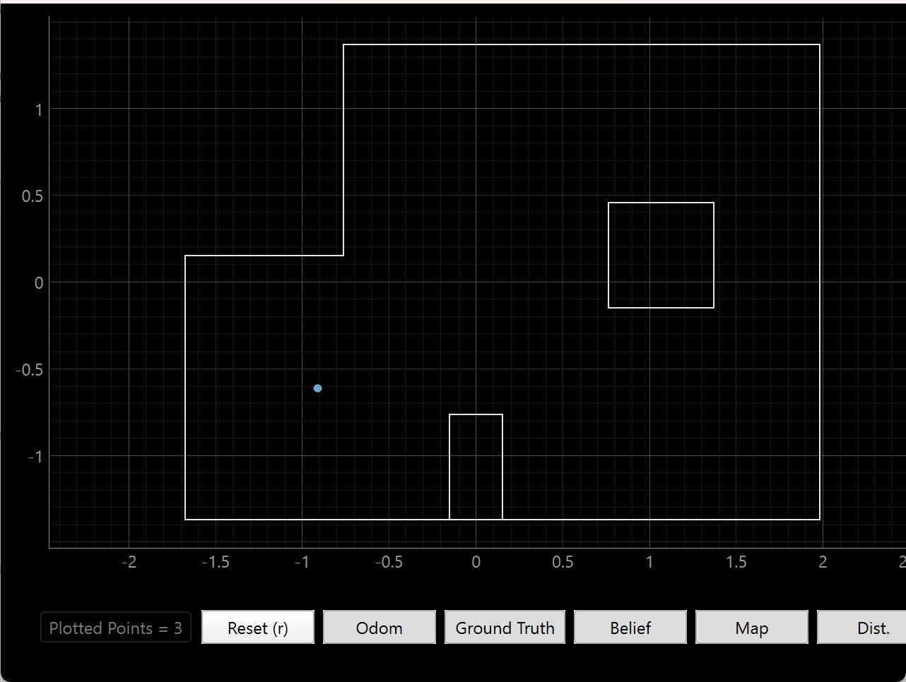
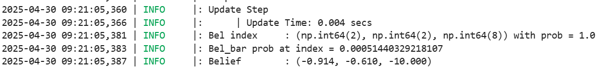
The result of the update step is incredibly accurate, likely because of the incredibly unique structure of the bottom left corner. There are nearby walls on three sides, and that trait exists nowhere else on the map.
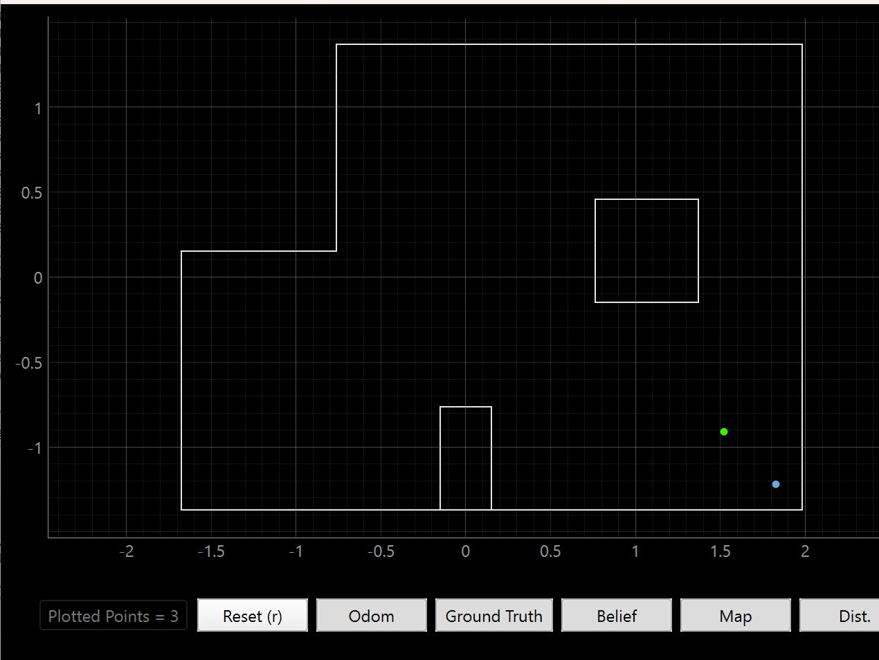
(0, 3)
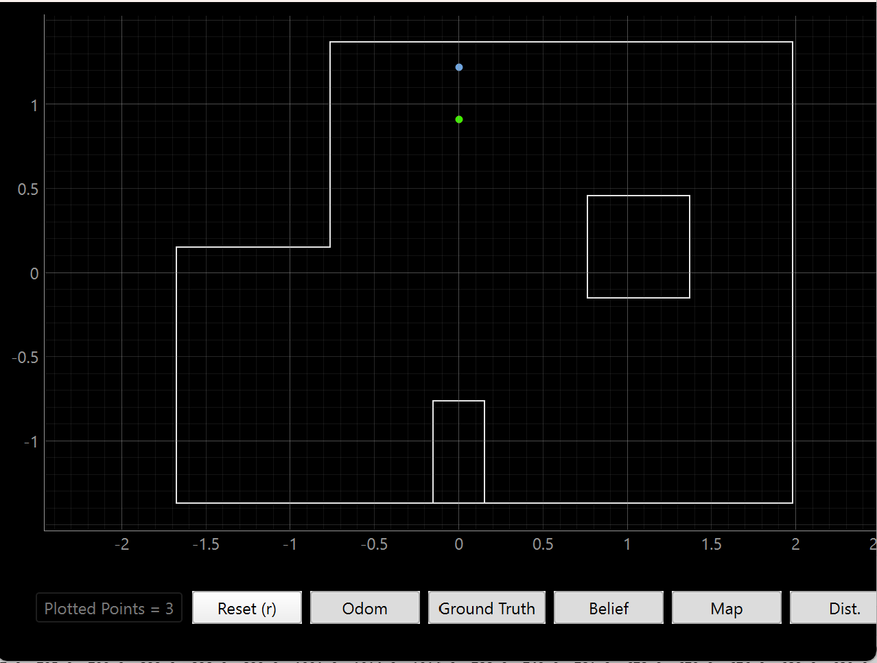
This position had a slightly off prediction, and that is likely due to the similarity of the map in that area. The robot would observe the same thing to the left and right of it even if the position varied up and down from the ground truth. Since we only get a few readings of the box and the top wall, it makes sense that the prediction is not perfect in one go.
(5, -3)

The prediction is much closer to the corner than the ground truth, and I suspect that may be because of how much of the map is visible AND far away from the robot. Errors in readings in both heading and range can cause the update step to veer in either direction.
(5, 3)

This prediction suffers from a similar problem to (0, 3) but in the opposite direction. The same indistinguishability along small vertical differences still applies, but I suspect that this is because the robot’s imperfect turn makes the TOF think that the box is closer than it actually is.
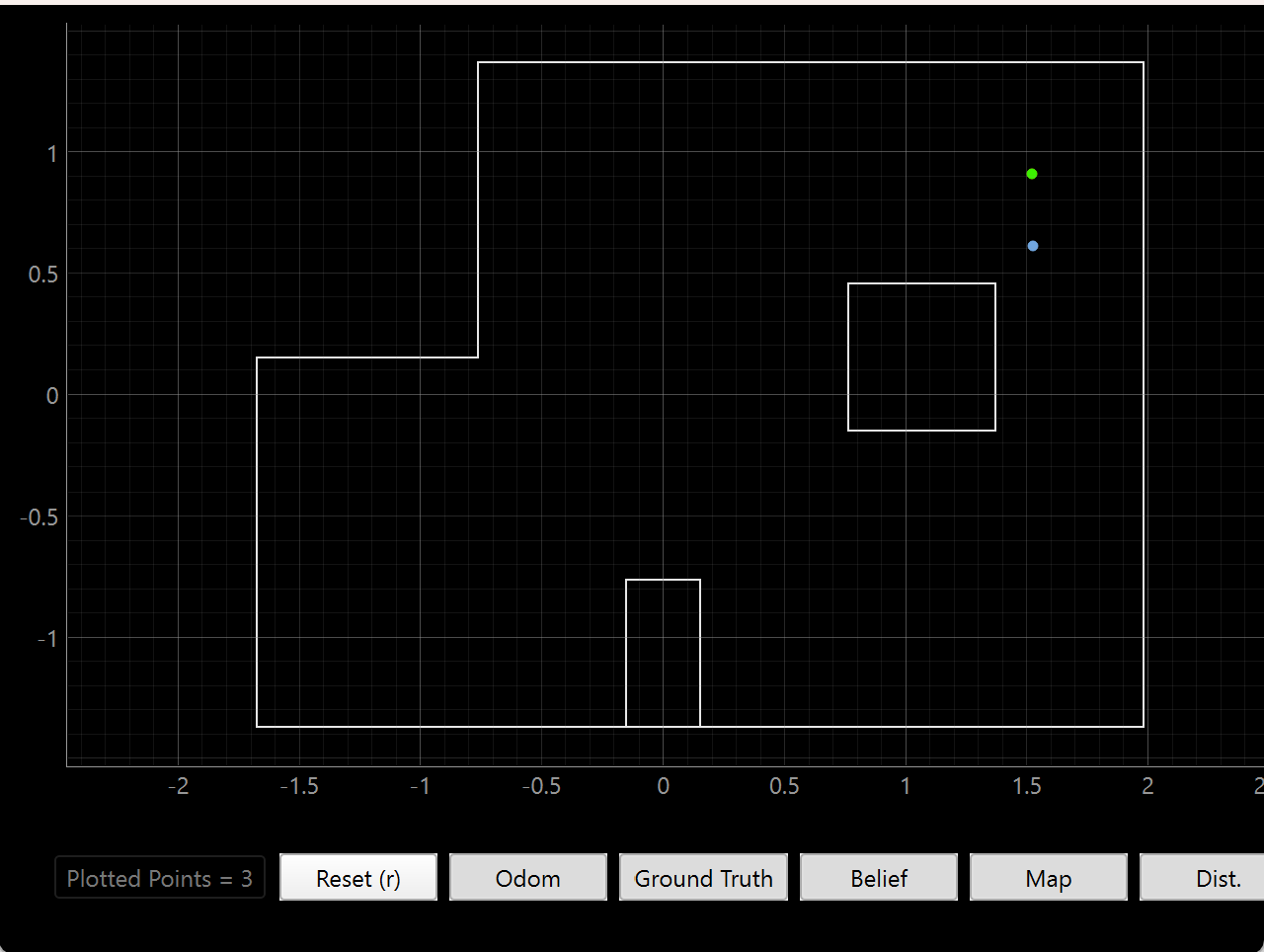
(0, 0)
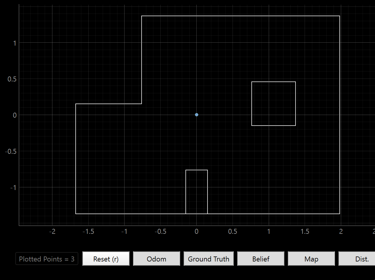

The origin prediction is as perfect as the (-3, -2) prediction because of how distinct the observable features are. Any variation in any direction would cause a huge change in what the robot observes, so the filter is able to narrow it down to the exact point.
Acknowledgements
- I’d like to give thanks again to Stephan Wagner for providing the idea for a more robust PID routine. Before I was having trouble with jerky motion because I was trying to get to the setpoint in one PID motion, effectively rendering integral control useless. Now, I use a smaller control to steadily get to the goal, which worked well for our tasks in Lab 11.