Lab 4: Motors & Open Loop
Prelab
For the prelab assignment, we were asked to think about how we were going to wire the Artemis to the motor drivers. I chose to use the analog pins 2, 5, 12, and 15 because they were evenly spaced out. This would minimize effects of crosstalk between pins, compared to using adjacent pins. The type of pin was irrelevant so long as we were able to send a PWM signal to it, which the analog pins are capable of.
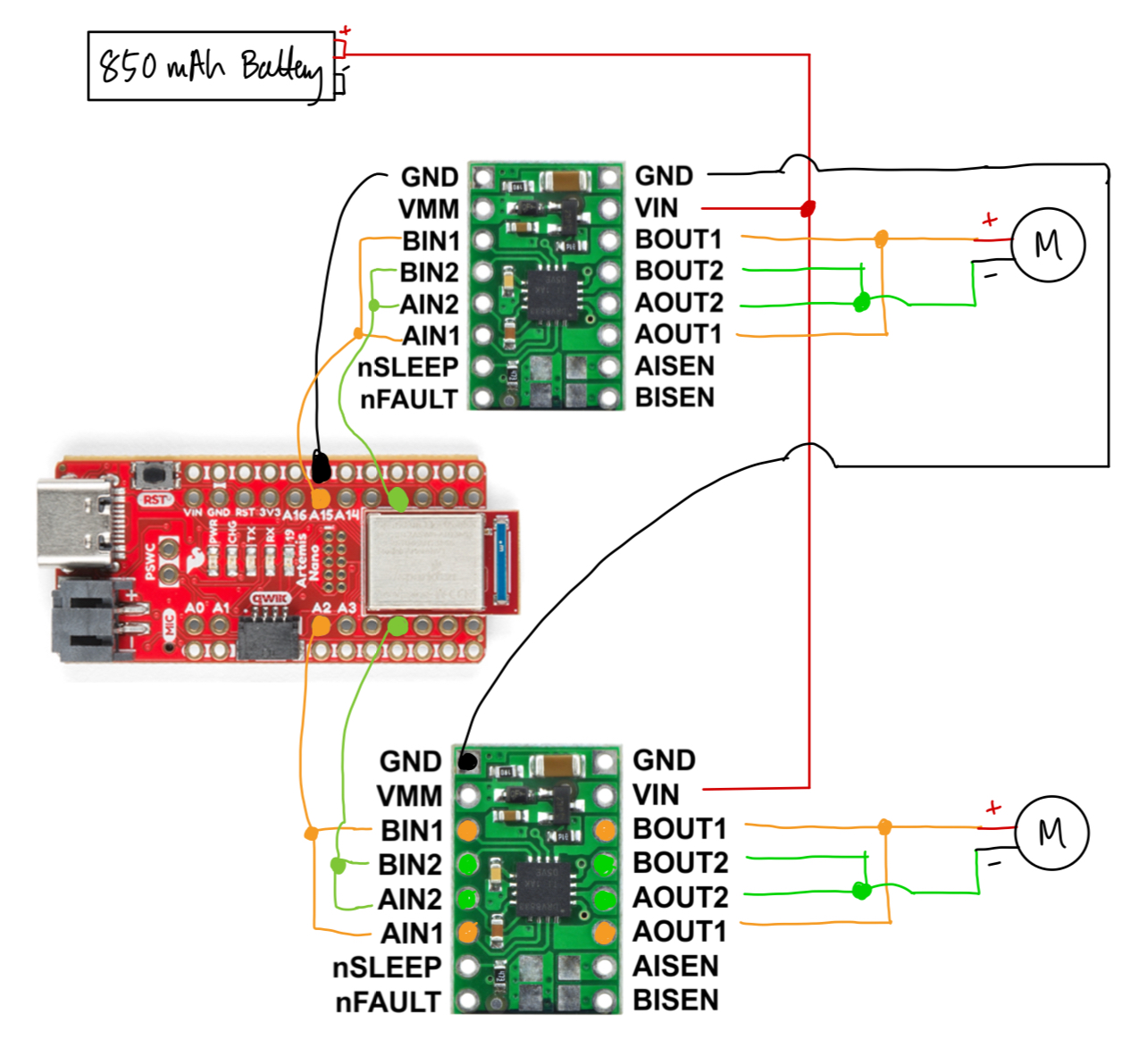
We also want to use different batteries for the Artemis than the motors because we want to maximize current draw to the motors for maximum speed. This also allows us to use the larger 850 mAh battery on the motors exclusively. It also allows us to decouple the microcontroller from the motor, which helps us prevent EMI from the motor to the IMU which must be connected to the microcontroller.
Testing PWM
After soldering the connections, I labeled and defined the pins with a motor number and pin number (either 1 or 2), as follows:
//Left
#define M1_IN1 5
#define M1_IN2 2

//Right
#define M2_IN1 15
#define M2_IN2 12
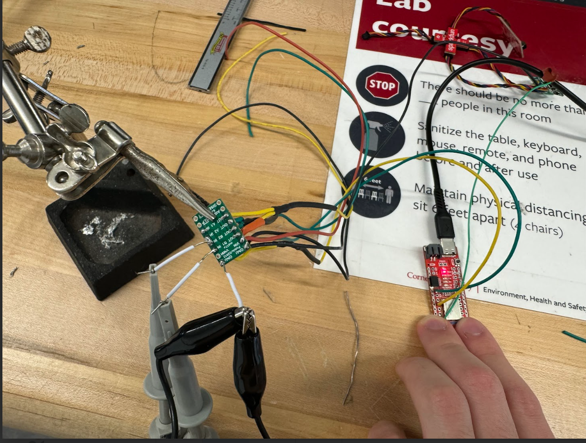
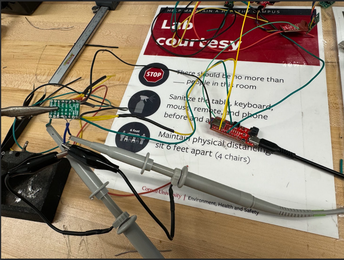
To test the PWM output from the Artemis, I conducted two tests on the two pairs of analog pins that I would use for the two motors. In each setup, I soldered temporary jumper wires so I could connect my oscilloscope to the motor drivers. The power supply was connected to Vin and ground via alligator clips, and set to 3.7 volts because the battery outputs the same voltage. I used the following Arduino snippet to pulse the PWM signal from 0 to 255 on both pins:
// Cycle PWM from 0-255 for in 1
for (int i = 0; i < 255; i++)
{
  analogWrite(M1_IN1, i);
  analogWrite(M2_IN1, i);
}
analogWrite(M1_IN1, 0);
analogWrite(M2_IN1, 0);

delay(500);

// Cycle PWM from 0-255 for in 2
for (int i = 0; i < 255; i++)
{
  analogWrite(M1_IN2, i);
  analogWrite(M2_IN2, i);
}
analogWrite(M1_IN2, 0);
analogWrite(M2_IN2, 0);
The pins 2 and 5 setup and resulting video:
;
The pins 15 and 12 setup and resulting video:
;
Testing the Wheels
I tested each side of the wheel spinning by supplying a constant PWM of 200 for each wheel:
analogWrite(M1_IN1, 200);
analogWrite(M1_IN2, 0);
delay(3000);
analogWrite(M1_IN1, 0);
analogWrite(M1_IN2, 0);
analogWrite(M2_IN1, 200);
analogWrite(M2_IN2, 0);
delay(3000);
analogWrite(M1_IN1, 0);
analogWrite(M1_IN2, 0);
The following two videos show this testing, where the power is still being supplied by the power supply.
Right wheels:
Left wheels:
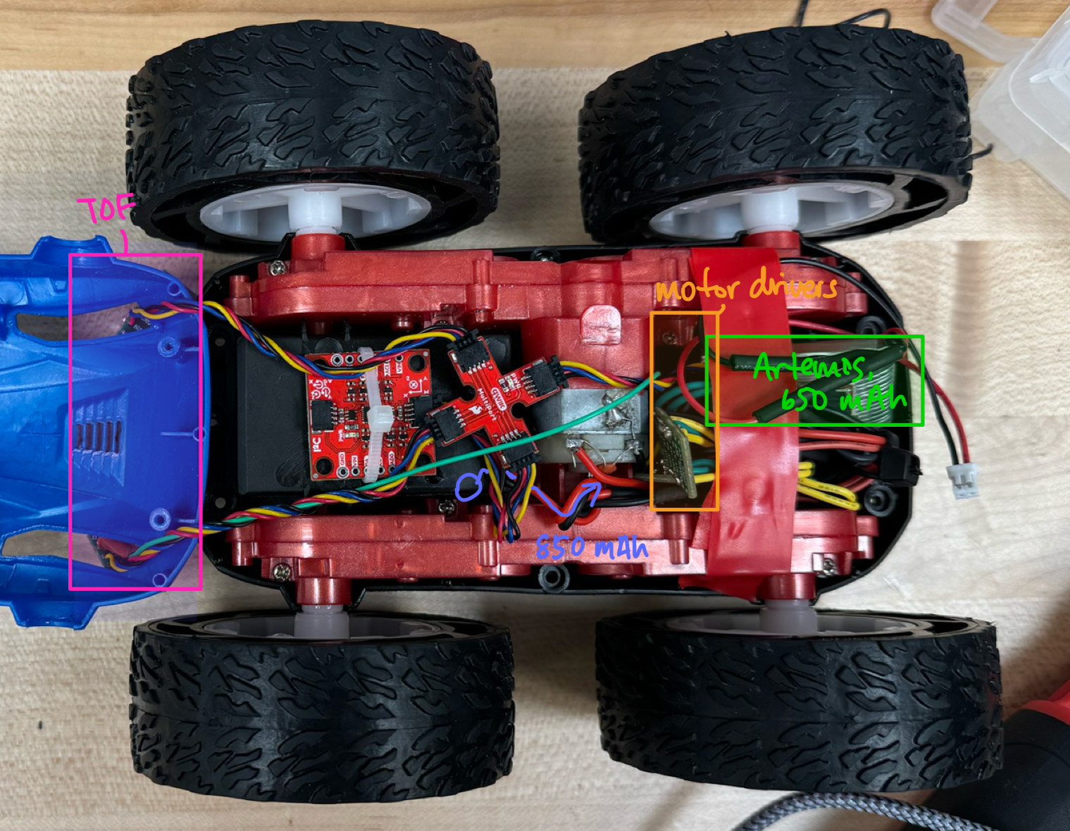
After verifying that each set of wheels works, I permanently soldered Vin and ground to the red and black leads that go through the battery compartment of the stock car. That way, I could plug in the battery on the other side and supply power to the drivers. After doing this, I tested all four wheels running at once:
Final Car Assembly
The
Lower Limit of PWM
To find the lower limit, I started at low PWM and increased it in increments of 5 on the ground to find a point where the wheels begin to spin and overcome friction (using the same code as above, swapping out 200 for lower values). The range I found the car overcoming friction is approximately a PWM of 35-40.
At 35 PWM, the car is essentially stationary.
At 40 PWM, the car is at the bare minimum for it to move. At the start of the video, the car doesn’t move at all. Then at the very end, when it finds a patch of slightly lower friction ground, it begins to move forward.
Naturally, the lower limit for PWM would vary as we change the frictional coefficient of the floor. This test was done in the Upson 264 lab, which has a tile floor. But if I was to instead travel on the carpeted floors in my apartment, the lower limit would be different.
Straight Line Calibration
To make sure the robot goes in a straight line, I first placed the robot down at high speeds and saw the direction that it went in. I placed it down in different spots of the floor to make sure that it wasn’t an imperfection in the ground causing the car to veer off. I observed that the car was very slightly shifting to the left at the end of a 2-meter movement forward.
To fix this, I introduced two calibration factors to modify the PWM input(so that it would be easier to adjust):
//The strength that each motor should run at.
//*** MUST BE <1. ***
float left_percent = 1;
float right_percent = 0.9;
This was used in my driving function:
void drive(Direction dir, int pwm)
{
  if (dir == FORWARD)
  {
    analogWrite(M1_IN1, int(pwm*left_percent));
    analogWrite(M1_IN2, 0);
    analogWrite(M2_IN1, int(pwm*right_percent));
    analogWrite(M2_IN2, 0);
  }
  else if (dir == BACKWARD)
  {
    analogWrite(M1_IN1, 0);
    analogWrite(M1_IN2, int(pwm*left_percent));
    analogWrite(M2_IN1, 0);
    analogWrite(M2_IN2, int(pwm*right_percent));
  }
}
I arrived at the ratio of 1:0.9 for my left and right wheels’ speed ratios by iterating once. I cut the right wheel’s speed by 10% to try to stop the car from slightly veering left.
After which, the car was able to go straight for 2 meters:
Open Loop
For the open loop demonstration, I wanted to make sure the car would go, turn around, then come back. I tested around with different spin times and speeds until I got it to pivot and turn. The code I used is attached:
void spin(Side side, int pwm)
{
  //Left wheels back; right wheels fwd
  if (side == LEFT)
  {
    analogWrite(M1_IN1, 0);
    analogWrite(M1_IN2, pwm);
    analogWrite(M2_IN1, pwm);
    analogWrite(M2_IN2, 0);
  }
  //Right wheels back; left wheels fwd
  else if (side == RIGHT)
  {
    analogWrite(M1_IN1, pwm);
    analogWrite(M1_IN2, 0);
    analogWrite(M2_IN1, 0);
    analogWrite(M2_IN2, pwm);
  }
}

void drive(Direction dir, int pwm)
{
  if (dir == FORWARD)
  {
    analogWrite(M1_IN1, int(pwm*left_percent));
    analogWrite(M1_IN2, 0);
    analogWrite(M2_IN1, int(pwm*right_percent));
    analogWrite(M2_IN2, 0);
  }
  else if (dir == BACKWARD)
  {
    analogWrite(M1_IN1, 0);
    analogWrite(M1_IN2, int(pwm*left_percent));
    analogWrite(M2_IN1, 0);
    analogWrite(M2_IN2, int(pwm*right_percent));
  }
}

void stop()
{
  analogWrite(M1_IN1, 0);
  analogWrite(M1_IN2, 0);
  analogWrite(M2_IN1, 0);
  analogWrite(M2_IN2, 0);
}

void loop() {

  drive(FORWARD, 235);
  delay(750);
  stop();

  delay(2500);

  //200 pwm * 1000 ms ~= 540 deg. on right side, slightly less on left
  spin(RIGHT, 200);
  delay(1000);
  stop();

  delay(2500);

  drive(FORWARD, 200);
  delay(750);
  stop();

  delay(2500);

  spin(LEFT, 200);
  delay(1000);
  stop();

  delay(2500);

  delay(5000);
}
Discussion
This lab I learned the importance of planning ahead.
References
- I referred to Mikayla’s website for guidance on wiring.